Introduction
This section explains all the principles of navigation on a 'blank chart' (i.e. we don't worry about all the chart information at this stage).
Navigation is the process of finding your way from one place to another. On land this has become pretty easy, because you can follow roads, and signs are provided to guide you. At sea it is different: you are in an open space with no roads or paths, so you need some different techniques to find your way around.
Generally these techniques are fairly simple and common sense, but we don’t use them in every day life, so there are a few new concepts to learn which are explained here.
We start with the fundamentals: how do you define something’s position? How do you measure distance, speed and direction? Using these building blocks we then explain how you can find your way from one place to another, and how you can determine (or 'fix') your position.
Position
In our normal lives we can use streets and addresses to define where something is. But in an open space we need to be able to define the position of a boat or destination port without reference to roads or landmarks. After that we can work out how to get from one place to another.
The standard way of defining positions is by two angles, latitude and longitude, measured form the centre of the earth, and every position on the surface of the earth can be defined in this way.
(In case you are not familiar with angles, a complete circle is divided into 360 degrees, written 360° - so a quarter circle or "rightangle" is 90°.)
Latitude 
Latitude is the angle which defines how far North or South you are.
Figure 1 shows how latitude is measured.
Every point on the surface of the earth has a latitude, and the angle is measured from the equator (0° latitude) to the North Pole in one direction and the South Pole in the other.
The further north or south you are from the equator, the greater the angle. At the limits the North Pole is at 90° North and the South Pole is 90° South. As shown in Figure 1, Land’s End is at about 50° North and Cape Town is about 34° South.
Longitude
Longitude defines how far East or West you are.
Figure 2 shows how longitude is measured.
We need to measure from a particular point on the earth. With latitude that is the equator, the natural centre line of the earth. With longitude there is no “natural” place to measure from, so navigators have chosen - somewhat arbitrarily - to measure from Greenwich.
The north-south lines of equal longitude are called meridians (named because mid-day happens simultaneously at all points along each of these lines) so the Greenwich meridian is 0° longitude. Every point on the earth’s surface has a longitude: New York is at about 74° West and Singapore about 104° East. The maximum easterly or westerly longitude is 180° - half way round the world from Greenwich.
Angles
When using latitude and longitude we need to be quite precise about the angle. A full circle is divided into 360° (degrees), hence 90° from the Equator to the Pole. One degree’s difference in latitude is about the distance from Leeds to Newcastle, so for more precise position fixing this needs to be broken down into smaller divisions.
So each degree is divided into 60 minutes (written 60'), and minutes are quoted to as many decimal places as you need.
You can then quote the position of the Bishop Rock light as:
49° 52'.33 North 06° 26'.68 West
and this defines the position to the nearest one hundredth of a minute (0'.01) which is about 20 metres distance on the surface of the earth. This is normally enough precision for navigating at sea.
(Historically each minute was further divided up into 60 seconds, so 27'.5 was written as 27' 30" . This is rarely used now, but you may see positions quoted that way in older books.)
Plotting Position on a Chart
Charts are special maps used for navigation at sea. (More about charts in a later section.) In order for navigators to be able to see the position of something marked on the chart, or to mark or plot the boat’s position on the chart, latitude and longitude are printed along the chart’s edges.
The chart is printed with North upwards, so latitude (giving North-South position) is marked down the sides of the chart and shows how far up or down the chart you are. Longitude (giving East-West position) is marked along the top and bottom edges and shows how far across the chart you are. Figure 3 shows how this works.
Note that on the bottom of the chart in Figure 3, the numbers - longitude - increase from right to left, which may catch you out - but it's obvious why this is, because the West longitude increases the further West you go. Always check the numbers, or you may get caught out if, say, you've been using a UK West Country chart and you switch to the Med (East Longitudes, increasing from left to right).
Distance and Speed
Navigators find it convenient to measure distance using a unit that relates closely to the measurement of position. The unit they use is a nautical mile (also known as “Sea Mile”) and it is defined as one minute (1 sixtieth of a degree) of latitude. This is shown on figure 4.
It is important to remember that this is latitude (on the side of the chart) not longitude (on the top and bottom). Latitude angles give virtually constant distances wherever you are on the earth, but longitude angles do not. (That's because the meridians get closer to each other as you move away from the equator towards the poles, as you can see in figure 2).
On land we use miles per hour for speed. So at sea speed is measured in nautical miles per hour, known as knots (some people say "knots per hour" but this is rubbish).
A nautical mile is about 1.15 statute or “land” miles, or 1852 metres. So 20 nautical miles is 23 land miles, and 30mph is 26 knots.
There is one other distance unit that you need to be aware of: a cable is one tenth of a nautical mile, and is just under 200 metres. It is used in pilot books, usually in the context of estimating distance, e.g. "anchor about one and a half cables south of the rocks".
The Log
The log is an instrument on the boat which measures the distance you have travelled through the water, giving a simple reading of nautical miles. From this it can also work out the speed at which you are travelling, displayed in knots. Use of the log is described later.
Direction
The next thing we need to find our way from one place to another is a measurement of direction. Once again, this is done by angle.
We are all familiar with the directions North, South, East and West. Years ago directions were expressed by subdividing these into the points of the compass, but this is slightly unwieldy with directions like “south-east by east” and “south-south-east”.
Now a simpler method is used and we measure directions in degrees, clockwise from North (see figure 5).
So East is 090°, South 180°, West 270° and North 0°. When saying a direction like 90° we say “zero nine zero” so it can’t be confused with, say, 19°.
We still use directions like "south-east" occasionally, or say “due West” to mean exactly West, or 270°.
The Magnetic Compass
The magnetic compass is one of the most important tools for the navigator, and it has been around for thousands of years.
Most people will remember learning about magnets at school. Very fortunately for navigators, the earth acts as a giant magnet, with the points of magnetic attraction very close to the North and South poles.
So the “north-seeking” end of an ordinary magnet will always point to the North if it is allowed to swing freely, provided there are no other magnets or lumps of iron to interfere with it.
Variation
There is a small problem, though, because the magnetic North pole is not in the same position as the earth’s North pole. The compass points to magnetic North, and this isn’t exactly the same as true North (the direction to the North pole). There is generally a difference of a few degrees between the directions of the two Norths.
This difference is called magnetic variation, and it differs according to where you are on the surface of the earth. It also changes with time, but the changes are fairly slow and predictable, so the chart will tell you the magnetic variation for the area you are interested in.
Figure 6 shows a typical compass rose as it is printed on a coastal chart. The outer rose shows true directions, and the inner one magnetic directions. The variation at this position, on 1st January of a given year, is printed on the inner rose, together with the rate at which it is changing.
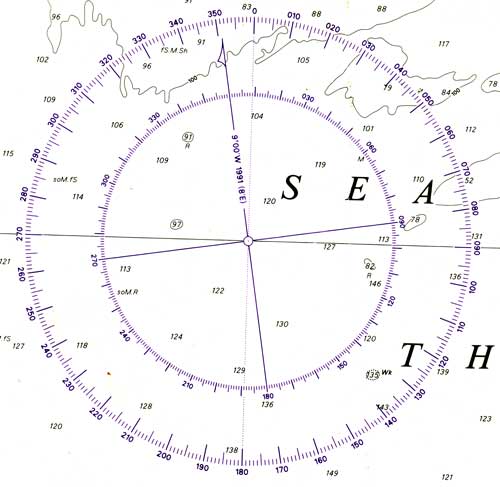
So to adjust for variation you simply add or subtract a (small) number of degrees, to get from magnetic direction to true direction and vice versa. Variation can be either East or West, and the following examples show how the correction is used:
If variation is 5° WEST:
-
magnetic is always 5° GREATER than true
-
a magnetic compass reading of 105° will convert to a true direction of 100°
-
a true direction of 270° will be a magnetic direction of 275°
If variation is 8 degrees EAST:
-
compass always 8° LESS than true
-
A magnetic compass reading of due North (000°) will convert to a true direction of 008°
-
A true direction of 180° will be a magnetic compass direction of 172°
If your correction takes you "through" north (rare, but much beloved of theory examiners) remember that 368° should actually be 008°, and -5° should actually be 355°. In other words, add or subtract 360.
Not surprisingly, it can be difficult to remember whether to add or subtract the variation correction. One mnemonic to help is:
“Variation is WEST, compass is BEST [i.e. greater number of degrees]
Variation is EAST, compass is LEAST” [i.e. lesser number of degrees]
The compass rose on the chart usually (but not always) shows both true and magnetic direction (as in figure 6) so you can use this to check that you have got the conversion the right way round.
It is generally easier to work in true on the chart (because the edges and lines on the chart are true North/South and true East/West). Convert to magnetic when you are working out a course to steer: or convert from magnetic to true when plotting on the chart a bearing you have measured with a compass.
Whenever you write down a direction, write T or M after it to remind you whether it is true or magnetic.
Deviation
A ship’s steering compass may need a further correction known as deviation. This arises because the compass may be close to magnetic materials that cause a small inaccuracy in the way that the compass points.
The size of the deviation error will generally depend on the direction the ship is pointing in. It needs to be measured from time to time, and a “deviation card” will be produced to show the error for each direction of the ship. Figure 7 shows examples of how this might be presented. 
With a hand-held compass you ignore deviation, because it is not used in a fixed position on the boat: take care to keep it away from metal objects. Also if deviation is small, it is often ignored.
Deviation error is also stated as East or West, and corrected in exactly the same way as variation. The same mnemonic rhyme applies.
Estimating Position
You have now learned the basics of position, distance, speed and direction. All the processes of navigation use these basics.
This section contains some ADVANCED CONTENT for Coastal Skipper, which is more than you need for a practical Day Skipper course. Most people will be happy to study it anyway, but in case you get stuck and worry about it, or haven't got time for it, you can stop reading if the paragraph is coloured like this one.
As a navigator, your problem is to find your way from one position to another position, and to know where you are along the way so that you can avoid any dangers along the route. Let us consider the basic problem of getting from A to B.
Tools of the Trade
The following sections talk about working on a chart, so it is appropriate to mention the tools you need when you are doing this.
Apart from the pencil (soft, for rubbing out) you need:
• dividers, for measuring distance on the chart
• a Breton Plotter or similar device for measuring direction, and for drawing lines in a particular direction.
Use of these tools is a practical skill, and describing their use in detail is somewhat outside our scope now. They are the only tools you need for the techniques that are explained next.
(Another possibility is compasses for drawing arcs of circles, but you can usually use the edge of a plotter instead. Parallel rules will make you look like a real navigator, but are not practical on a moving boat.)
Dead Reckoning
A chart marks the positions of the places you want to go from and to. You can also plot the boat’s position on the chart. So the simplest way to find your way from A to B (assuming there are no dangers in between) is:
• mark the positions of A and B on the chart, or find them if they're already marked
• draw a line from A to B
• measure the direction of this line (Breton Plotter)
• apply the corrections to get compass direction (variation and deviation - see above)
• steer in that direction using the ship’s magnetic compass.
The chart will also give you the distance from A to B. Measure this using a pair of dividers, and read off the side of the chart in nautical miles.
The ship’s log will tell you the distance in nautical miles that you have travelled through the water. Take a note of the log reading when you are at A, or set it to zero: and the log reading will then tell you how far you have travelled from A towards B - assuming for the moment that the water is not moving relative to the ground (i.e. no tidal streams or currents).
If you measure off the logged distance on the side of the chart (dividers again) you can mark your position on the line from A to B.
This is called Dead Reckoning (DR). You are finding your way and plotting your position purely by travelling in a straight line and measuring how far you have moved through the water.
Figure 8 illustrates this process.
Estimated Position
Dead reckoning is the simplest way to estimate the boat’s position, but there are two factors that can produce errors in the DR position:
• the first is that the boat may not be moving straight through the water in the direction you are steering in, and it is pointing in
• the second is that the water itself may be moving.
Both of these errors can be allowed for, and making these allowances gives the best Estimated Position or EP.
Leeway
The first of these is called leeway. It applies principally to yachts sailing close to the wind, but can also apply to a shallow displacement powered craft in a strong cross wind. Essentially, the boat may be moving through the water in a slightly different direction to that which it is pointing in.
We need a couple of new terms to explain this: the ship’s heading or course steered is the direction the ship is pointing in (as read from the ship’s steering compass), whereas the water track is the direction in which the ship is moving through the water.
The leeway is the difference between these, and it varies from boat to boat and under different conditions of wind and sea state. 
Logically in a yacht the water track will be further off the wind than the ship’s heading, (unless you have an angled keel, which could give zero, or even negative, leeway).
So the first thing you can do to improve on your DR estimate is to plot the water track rather than the course steered, and measure distance travelled against that. Figure 9 illustrates this.
Tidal Stream
The second correction is due to the fact that the water itself can be moving over the ground.
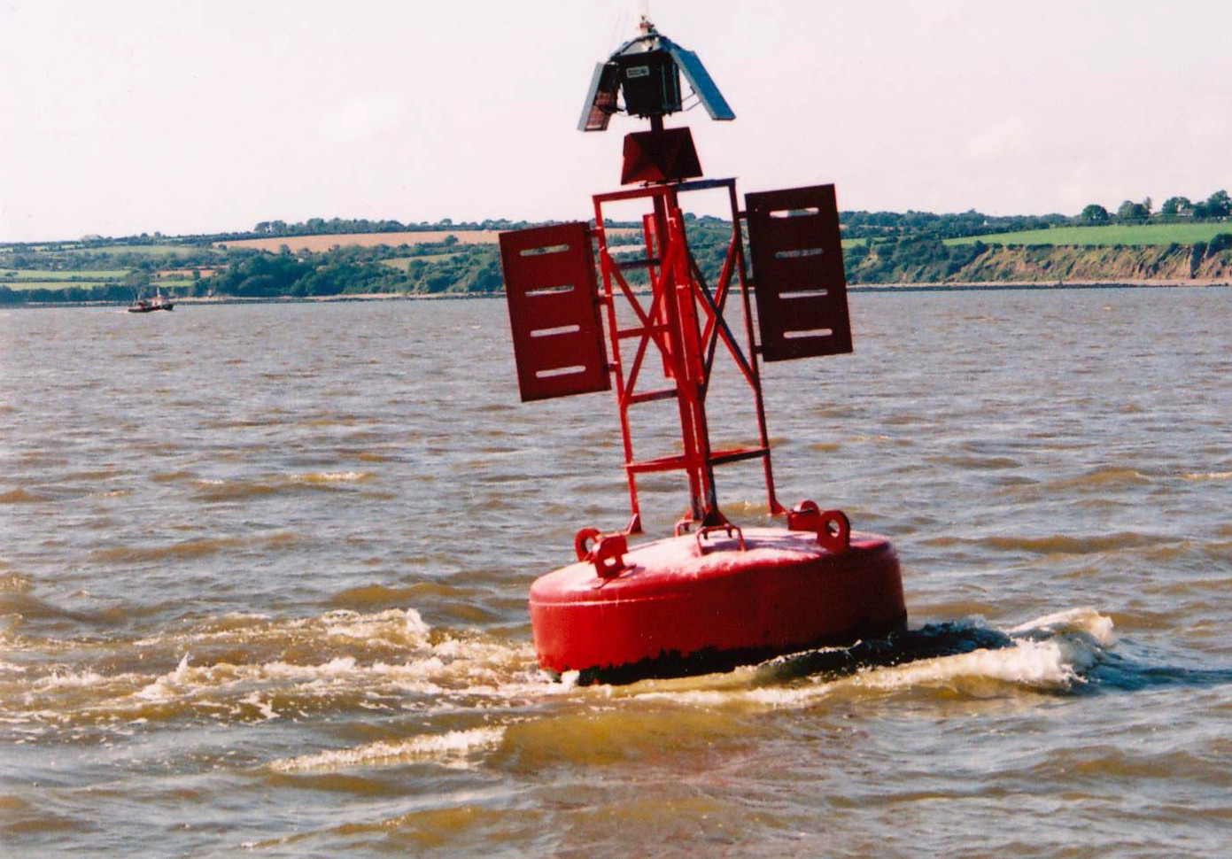
This idea can be very surprising to those who do not know the sea well, because when you are floating on the water you have no sense of it happening. It is only when you see the water moving against something anchored to the bottom, like a buoy or lobster pot marker, that you realise the water is flowing like a river. I know one skipper who has told innocent and gullible crew that a buoy moving through the water was being towed by a submarine, and that is exactly what it looks like (see photograph).
The most common cause of water motion in the seas around Europe is tidal stream. The motion of the water due to tidal streams can be measured and predicted. Chapter 2 explains tidal streams and how you can predicted them from tidal data.
For ocean sailing you may need to allow for currents. These are general movements of the water in the ocean and are reasonably constant and predictable. They are not tidal. Currents can generally be ignored for coastal sailing around British waters.
 Another term is introduced to help with this: ground track is the actual path of the boat relative to the ground, just as water track was the path through the water. The difference between the two is the movement of the water itself.
Allowing that the speed and direction of water movement can be calculated, this can be added to the movement of the boat through the water.
Mathematicians will recognise this as the addition of two vectors, but it is simple common sense: in a certain period of time you move a distance through the water, but in addition to that the water moves (i.e. you would have moved with it even if you had been stationary in the water). It is the same as walking on a moving walkway or escalator. Add the two together and you have the boat’s total movement as illustrated in Figure 11.
Plotting the EP
So to plot the boat’s EP you follow a slightly more involved process than the DR:
• estimate the leeway (say, 5° if you are sailing close to the wind - or zero if you are motoring, or sailing down-wind)
• draw the line from A in the direction of the water track, i.e. the course steered but adjusted for leeway
• read the logged distance, and mark that distance on the water track line from A
• from that point draw a line in the direction the tidal stream is running
• mark on that line the distance the tidal stream has run in the time since you left A, and this is your EP. Figure 12 illustrates this.
Course to Steer
From the diagram, you can see that we have estimated our position all right, but the trouble is, we're not going towards B! Ideally, we would like to adjust the direction that we're steering in, so that we DO get to B.
There are two ways that this can be approached. It is quite possible to work out the course to steer in order to get to B, provided we have good estimates of:
• leeway
• tidal stream - speed and direction - for the duration of our passage to B
• our own speed, for the duration of our passage
This also assumes that we CAN steer in the direction we want to, i.e. it isn't too close to the wind.
In practice, however, coastal yachtsmen rarely spend time working this out, because there is an easier option available to us - so I'll explain this first.
Course to Steer - Modern Practical Approach
I can hear traditionalists saying I'm teaching the lazy approach, but it's not lazy as long as you understand the principles behind it. We're going to use the GPS, but we're also going to check that we aren't making any silly mistakes.
First, measure the course from A to B off the chart. Make the adjustments for variation and deviation, and that's your first estimate of the course to steer.
Then, work out which way you think the leeway is going to take you (away from the wind) - and also look up which way the tide is taking you (see the chapter on Tides). Normally it will be reasonably clear from this that you are going to be pushed either to the left or to the right of your desired track to B, and you are going to have to steer slightly off your measured course, in order to compensate for this and track towards B.
So steer a little bit off the course you previously measured, so as to counteract tide and leeway, and you can use the GPS to give you the direction that you're actually moving in - your ground track (sometimes COG, or Course Over Ground). This needs to be close to the direction from A to B - and you can adjust the course steered until it is close enough. Note that the GPS can be set up to give you True or Magnetic direction: make sure you know which one it is giving you.
Make sure that you are steering off in a direction that makes sense, given what you know about the tide and leeway.
Beyond that, there are a few ways that you can check that you are still on the right track, or which side you've wandered off to. You need to make sure that B stays in the same direction (i.e. the direction you measured on the chart) as you move closer to it. If you can see B, you can check this with a hand bearing compass, and a transit with the land behind it if possible (see the section on position lines). If you can't see B, you could put its position into the GPS as a waypoint and check its bearing that way.
If the bearing towards B is increasing you're going to the left of the track, and vice versa. So if you are wandering off the track, adjust your course again. Figure 13 shows this.
Course to Steer - Theoretical Approach
The theoretical approach relies on estimating tidal speed and direction, and your own speed. It is only valid if these estimates remain valid - so if the wind drops and you slow down, you're going to have to re-calculate.
We described "adding" the movement through the water (speed and direction) the movement of the water itself (speed and direction), to get the "ground track" of the boat. Mathematicians call this vector addition (a vector is something that has both magnitude, in this case speed, and direction). What we now need to do is adjust one of these - the boat's direction - so that the ground track is in the direction we want.
The easiest way to do this is as follows:
• use the Breton Plotter to draw a line from A to B. This is the ground track we want.
• draw the tide vector from A.
 This is a line going in the direction the tide is going in. Its length is a representation of the speed of the tide, and the clever thing is, this can be in any units we want, as long as we stick to them. So choose a convenient scale off the side of the Breton Plotter (where there are several different scales marked) and draw the line, say, 2 units long for a 2 knot tide.
• from the end of this line, we need a second vector to get us back onto the ground track line.
This is our speed and direction through the water. We estimated our speed, so say that was 4.5 knots, draw a line 4.5 units long (same units) which gets exactly from the end of the tide vector back to the AB track. This is very quick if you use the side of the plotter, where the units are marked, and swing the plotter round till a line of the right length just fits.
• the direction of this second line is the direction of the water track we need and (ignoring leeway for the moment) the course we should steer.
• you can get one other piece of information out of this triangle: the length of the third side, along the AB line, in the same units, is the speed in knots at which we will travel towards B.
Measure the direction of the water track vector, apply corrections for variation and deviation, and then allow for leeway - adjust the course by 5 degrees or so into the wind if the wind is forward of the beam (otherwise you can pretty well neglect the effect of leeway).
Other Practical Methods
If you are going across the English Channel, which may be your first "serious" passage, a glance at the tidal atlas will show you that the tide is essentialy running East or West at any given time. The passage is going to take you quite a few hours, and you want to average the effect of the tidal stream over, say, 10 hours. So we take a slightly different approach to working out where we should steer.
Incidentally there is plenty of software available to run on, say, a laptop which will do this kind of planning for you. The software will typically contain a database of tides, and may even interface with a weather forecast! (It makes you wonder why you would bother to be on the yacht at all.)
But if you are a traditionalist or haven't got a laptop, here goes:
• mark on the appropriate page of your tidal atlas roughly where you will be, for each hour of the passage
• take a note of the predicted tidal stream at your expected position for each hour, East or West. It's easiest if you write this down in two columns, one for East and one for West. In this way you are noting how far the tide is predicted to push you in an each hour (knots x 1 hour = nautical miles)
• add up both columns and "net" them - subtract one from the other - and note whether the net total is East or West.
You now know that you are going to be pushed a small number of miles to East or West - so head for a point on the coast which is that number of miles further to the West or East of your destination.
Typically, if your passage time is around 12 hours (say Poole to Cherbourg) the East and West movement will very nearly cancel each other out. Once you have worked this out a few times you probably won't bother and just aim straight for your destination!
By the same token, it's interesting to note that this kind of planning becomes less and less relevant if you are doing longer passages. What you do is ignore the tide until you get reasonably close to your destination - then work out a stragegy so that you end up, if possible, slightly 'up-tide' of the entrance, so that the tide helps you close in at the end.
Position Fixing
In the previous section we described how we can calculate an estimated position from distance logged, course steered, leeway and tide. But the estimated position is only an estimate. Its accuracy depends on how well we can steer the ship in a straight line, the accuracy of the compass and log and how well we have estimated the effects of tide and leeway.
The inaccuracies will accumulate over time. The navigator therefore needs to check the ship’s position regularly, if possible. This is done by fixing the position, and (luckily) there are quite a number of ways of doing this.
Broadly, you can fix your position by means of:
• electronic devices
• observation of landmarks on shore or navigation aids (bouys) anchored at sea (or objects like the sun and moon, for ocean sailors).
Global Position Fixing (GPS)
This is the most widely used electronic device for fixing a position. It works by picking up signals from a set of satellites continuously orbiting the earth. By knowing where the satellites are (information they continually broadcast) and the time delays of receiving signals from each satellite, the GPS receiver can work out the distance from three or more satellites and from that work out its position on the surface of the earth.
The user simply reads the latitude and longitude from the display, making these devices very simple to use.
GPS receivers are excellent position fixing devices. They are relatively inexpensive and generally reliable, although a number of them failed during the 1999 “week number roll-over” event (which will be repeated every 19 years). GPS is a military system, so theoretically the military may decide to shut it down, and from time to time there are local jamming exercises; but hopefully this is a small risk.
Despite its reliability and accuracy there are dangers, however, in becoming over-reliant on any electronic device, particularly where electric power and salt water are closely associated.
The accuracy of the position varies, and is generally close to 20 metres: adequate for most purposes, but remember that the accuracy is slightly less than the precision of the latitude/longitude readout (often three places of decimals, i.e. 2 metres) might suggest.
A higher order of accuracy is provided by Differential GPS or DGPS. This system relies on a ground station, which senses the GPS signals and works out the error in the GPS position (the ground station knows where it actually is!). It then transmits this information to nearby GPS receivers, which can then refine their own positions by applying the error. There was a time when ordinary GPS accuracy was quite severely restricted for civilian users, and DGPS was useful for mariners: now, however, ordinary GPS is quite accurate enough for our purposes, and DGPS is more relevant to people like surveyors.
GPS receivers are able to be set up to a number of different chart datums, which have been used for making charts in different parts of the world. Basically, the definition of Latitude and Longitude is not identical on all charts, largely because the Earth is not a perfect sphere. Differences are relatively small, but large enough to cause problems if your GPS is set up on the "wrong" chart datum. So CHECK that it is set up for the datum of the chart you are using.
A final point: GPS can be MORE ACCURATE than the chart you are using, particularly if you are navigating in a remote part of the world, where the person who drew the chart (probably in the 19th century) was using a sextant. So you may know your position very accurately, but unfortunately the person who drew the chart didn't know the latitude and longitude of the rock to nearly the same accuracy. In these locations you navigate by observing landmarks etc - or stay well off-shore.
Hyperbolic Systems: Decca, Loran
Before the advent of GPS a number of areas of the world had other electronic navigation systems, which relied on ground-based transmitters. Some of these still operate, although they are now being phased out in favour of GPS, which has so much wider coverage and is cheaply available.
In principle these systems are just as easy to use as GPS receivers, with a simple readout of latitude and longitude (on modern sets - earlier ones needed specially marked charts) and all the usual route and waypoint functionality. However they are subject to slightly more exotic errors. Advice here is: if you are using such a system (and you are now a minority) study the handbook carefully so that you fully understand the way the system should be used, the kinds of error that can happen, and how to correct the instrument if they do occur.
Position Lines
There are a number of other ways to work out your position that do not involve electronics. Practically all of these involve drawing a line on the chart, such that you know you are somewhere on that line. This is called a position line.
If you can draw two or more that intersect, you have a position fix. However you measure and draw your position lines, there are likely to be some inaccuracies or errors - this is absolutely inevitable with practical navigation. 
But by choosing position lines well, the effect of the errors can be reduced. The best position fix is obtained from position lines that intersect at a good angle, ideally 60° to 90°. If they intersect at a narrow angle, any errors you have made in drawing the position lines can result in quite a large uncertainty of position (see figure 15).
Three Bearing Fix
By far the most common and useful of these fixes is the three bearing fix, which is derived from measuring the direction or bearing of two or more charted objects that you can identify and see:
• you take a careful measurement of the bearing of each object, using a hand-held compass
• you then adjust the magnetic bearing by the magnetic variation to get the true bearing (subtract westerly variation or add easterly) 
• you then draw a line on the chart through the charted object at exactly the bearing measured (see figure 16)
• this is your position line for that object (we know we must be somewhere on that line in order to measure that bearing).
This is repeated for another object, and where the two cross is our position fix, subject to errors of measurement and plotting. If you do the same with a third object the position line should intersect where the other two intersect. In practice it will not quite, because of the errors. Instead the three lines will form a small triangle, known in the trade as a cocked hat (now a seriously outdated metaphor).
As long as the triangle is nice and small you can be confident that you have a good position fix. See figure 17.

If the triangle is very large, it is likely that you have made a mistake or gross error in the process. One of the position lines must be wrong, so start by checking that you have plotted the lines right, then make sure that the measurements were OK, and check your conversions from magnetic to true (it really helps if you write everything down, so that you - or someone else - can check it later).
Finally, check that you were sighting the objects that you identified on the chart. The latter point is very often the most likely and most confusing error (see figure 18).
You may be able to do a fourth position line to see which one of the first three was wrong.
Remember: if you had only done two position lines in the first place you might never have noticed this gross error. This illustrates the "golden rule" of navigation, which is that you WILL make mistakes, so ALWAYS try to check one thing against another: e.g. does your position fix make sense, given your logged distance from your last known position?
Other Position Lines
There are several other ways of getting position lines, and where any two or more intersect at a good angle you can fix your position.
Distance Off
If you can determine your distance off, i.e. the distance between your vessel and a landmark which is marked on the chart, you can draw part of a circle using the landmark as the centre - this is a position line.
A radar can give you the distance from land. The distance can also be determined by measuring the vertical angle of an object above the horizon.
Vertical angles can be measured with a sextant, and the almanac has tables for working out the distance off. This is a less frequently used method.
Or you may be able to see a lighthouse just appearing above the horizon. The last one is of particular interest because lighthouses are always marked on the chart, they are easy to identify by their light characteristics, and the rising and dipping of a light is simple to observe in clear conditions; you can just see the clear light as it rises above the horizon and the loom when it dips below.
The nautical almanac has a table for distance off when rising or dipping. You need to estimate the height of your own eye above sea level, and also the height of the light - which will be marked on the chart and for which you should allow for height of tide if you want to be precise.
Figure 19 illustrates this.
If you take a bearing on the light at the same time, this will give you two position lines crossing at rightangles - potentially a good fix. You must make sure you have identified the light correctly, though, and another position line from a different source will help to confirm this.
Depth Contours
Depths are marked on the chart, and so are underwater contour lines known as depth contours. You can measure depth with the echo sounder, and allowing for the height of tide (explained in the Tides section) you can tell when you are on the contour line. See figure 20. 
This is a useful technique when the depths are varying in a fairly regular way, on the edge of a channel or shoaling gently towards the land for example. It is not so useful if the sea bed is very irregular - the depth contour lines will be squiggling around all over the place and won’t make such good position lines. Nor is it very useful if the sea bed is almost flat, with the depth changing by a couple of metres in half a mile - it just won’t give you a very accurate position line in that case.
Transits
This is one of the simplest and most accurate position lines. A transit is when two things you can see line up.
If two objects that are marked on the chart can be seen to line up, you are on a position line that can be drawn through those two objects. See figure 21.
Transits are frequently arranged deliberately, and marked on charts and in pilot books, to guide you into a safe channel or harbour. But you can also spot your own, and if you see a good transit - like two headlands coming into line - it is often worth using it quickly for a position fix.
Note that transits which are "arranged" and charted to guide you into harbour etc should always have a bearing quoted, so that you can check that you have the correct transit marks (the Golden Rule again). And they are always arranged with the further object, or light, higher than the nearer one - if you know this you can work out which way to go to bring them in line.
Sectored Lights 
Some lights are arranged so that they shine different colours in different directions. These are called sectored lights, and they and their sectors are marked on the chart. When you see the light as one colour you know you are in that sector (see figure 22 ) and when the light changes from one colour to another you are on the position line that defines the edge of the sectors.
Radio Direction Finding
Some radio receivers are designed so that the aerial can be rotated, and you can tell when it is pointing straight towards the transmitter. This can be used to draw a position line in exactly the same way as when you take a bearing with a hand bearing compass, and is known as radio direction finding.
As an early form of electronic navigation this was quite widely used in the past (and still is in aviation) with radio beacons set up and marked on the chart like radio wave lighthouses. It is less accurate, and now much less widely used, than GPS.
However in an emergency, the Coastguard can give you a position line by listening to your VHF radio transmission from his direction finding aerials (marked on the chart). You can then draw the bearings he gives you onto your chart as position lines.
I heard this used on a foggy morning just after the “week-number roll-over” event on GPS - when a yacht was making landfall after a cross channel trip, and both of his GPS receivers were refusing to work. I also heard it when two of my friends were caught in a sudden gale off Rame Head near Plymouth - they had set out on a beautiful morning (my fault for advising them to go) and the boat being new to them, they hadn't yet got their GPS working...
Horizontal Angle between Objects
This method is seldom used because not many yachts carry sextants and the position line is difficult to plot. If you measure the horizontal angle between two landmarks, it is possible to construct a circle of all the possible positions where that angle between the objects could have been measured, thereby giving a circular position line.
Although it can be very accurate, this is a somewhat cumbersome method of getting a position line.
Astronomical Navigation
An astro navigation sighting, where you measure the angle above the horizon of the sun, moon, planets or stars and work through the sight reduction procedures, will give you a position line. (It is, in fact, a very large circle but it can be drawn as a straight line for the ten miles or so that you are interested in). So you have to make at least 2 observations to get a position fix.
Transferred Position Lines
This is a very useful method if you can only get one position line - say, a bearing to a known object - and some time later you are able to get another one, perhaps a new bearing to the same object.
By knowing how far you have moved between the two observations you can move, or transfer, the first position line by the same distance and direction that the boat has moved in. Where this transferred position line crosses the new position line, you have a position fix.
Figure 23 illustrates this process.
• at time 1 you measure a bearing and draw a position line 
• as you sail along the coast you estimate the movement of the boat using the EP technique - logged distance, leeway and tidal stream
• at time 2 you measure another bearing and draw a second position line
• re-draw the first position line parallel to the original but moved by the same distance and direction the boat has moved in. Just take any point on the first line, work out an EP from that point for time 2, and draw a new line, parallel to the first one, running through that EP
• the fix is where the second position line and the transferred position line intersect.
The method relies on the accuracy with which you can estimate the movement of the boat between the two fixes, hence the accuracy of the log and the tidal estimate are important.
Clearing Lines
Sometimes when navigating you don’t need to know exactly where you are you are. It may be enough to know approximately where you are, and to be sure that you are clear of dangers.
If you can draw a single position line, like a bearing on an object for example, and know that you are not on the line but to one side of it, this can tell you enough about where you are to keep you out of danger. The line is then called a clearing line, and is shown in figure 24. 
All the methods for getting position lines can also be used for drawing clearing lines; in particular they can be transits, light sectors or bearings on a landmark or navigation mark. Obviously depth contours can also be used to keep away from shallow water dangers.
Clearing lines are one of the best and most useful tools for pilotage (where you are finding your way around close to shore and dangers). One observation can tell you if you are safe or not, which can be far quicker than plotting your position from the GPS.
Another top tip - say you are using a position line which is a bearing to a landmark. If you put that landmark into the GPS as a waypoint, then the GPS can give you the bearing to the landmark - which is a useful back-up (say you can't see the landmark because it's misty) and check of the hand bearing compass observations.